Power drive your Raspi
 Edit this page
Periph just gained super powers (in the literal sense) to enable increasing or decreasing the power push on the GPIO pads. This will be available in the next release.
There are 2 output functions that can adjusted:
- The slew rate limiter, which limits the speed at which the GPIO changes from one level to another.
- The drive current, which limits how much total power is pushed on the line.
The broadcom processor has flags to configure the physical properties of the GPIO pads. periph’s bcm283x driver now expose a function to configure these. The driver also gained the ability to disable input hysteresis but this is for another post.
The program (attached at the end of this post) runs 4 pulses in 4 different GPIO pad configurations:
- 2mA drive with slew limited
- 16mA drive with slew limited
- 2mA drive with slew unlimited
- 16mA drive with slew unlimited
The default is 8mA with slew unlimited.
This screenshot was taken without any load, e.g. nothing connected to the pins except the oscilloscope itself:
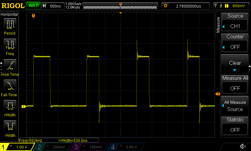
When no significant load is on the GPIO pad, both the 16mA setting and unlimited slew increase the signal overshoot (going over 3.3V or under 0V).
The 16mA had a large effect on the High→Low transition, while the slew limit had more effect on the Low→High. Enabling slew limiting and reducing the current drive gives a vey clean signal as seen on the first pulse.
Keep in mind that these oveshoot are by definition transient and will vary from pulse to pulse.
With load
With a LED driven by the GPIO, the tension (Volt) of each pulse is much lower, and the 2mA clearly has more trouble driving the LED, not able to attain 3V and the 16mA barely makes ~3.1V.
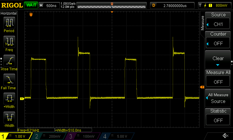
The effect of slew limit is not visible at all when there’s a significant load on the GPIO pad.
As we saw above, slew limiting is mostly effective when the current draw is very low, that is, the impedance of the load is high.
Delays
While not shown in the screenshots in this post, there’s a delay between when these values are set and when they effectively take effect. The call to change the GPIO pad settings seems to take nearly 500ns, as shown in the larger valleys in the screenshots.
You can play with the program below to see the effect, this is especially visible in the loaded situation when switching from 2mA to 16mA, as a following pulse has a voltage bump in it.
GPIO groups
The fact that GPIO 0 to 27 are configurable as a group and that the Raspberry Pis do not expose GPIO 28 to 45 is a downer, as this would have provided a mean to use two different configurations simultaneously, i.e. one group setup for communication and one for high current load.
The Raspberry Pi power source is designed for a fairly low average current draw per GPIO pad, so do not expect to be able to drive several GPIO pads at 16mA level without smelling some burnt odour.
Conclusion
Both the current drive strength and the slew limiting have effects on the signal quality, but their effect is load dependent. The current drive strength must be high enough in the situation where the GPIO is sourcing current, but otherwise, it is preferable to keep it low to reduce oveshoot.
On the other hand, the overshoot is not necessarily bad and can help in some situations like when communicating over long wires where parasitic capacitance may affect signal quality. The actual transient effect will be affected by the load capacitance and inductance, so depending on what you connected, the result will vary.
In practice, the default values are good and it is recommended to look at the signal quality with an oscilloscope on a loaded system to find the best trade off, and not try to take a guess.
Program
The program does a few things to make sure things work in a reproducible way:
- Lock the goroutine to the thread and disable GC, to reduce Go runtime hickups for this demo.
- Run a spin loop so the linux CPU governor kicks the core into high speed.
- Spin loop between state transitions, as it was observed that it takes seveal tens of nanoseconds to see the effect.
In practice, the program is still very dependent on the goodwill of the operating system.
package main

import (
    "fmt"
    "log"
    "runtime"
    "runtime/debug"

    "periph.io/x/periph/conn/physic"
    "periph.io/x/periph/host"
    "periph.io/x/periph/host/bcm283x"
)

func main() {
    if _, err := host.Init(); err != nil {
        log.Fatal(err)
    }
    // Try to change it once, if it worked, the rest will work.
    if err := bcm283x.PinsSetup0To27(2*physic.MilliAmpere, true, true); err != nil {
        log.Fatal(err)
    }
    fmt.Printf("Running\n")

    // Reduce interference from Go runtime.
    debug.SetGCPercent(-1)
    runtime.LockOSThread()

    // Spin the CPU a bit to make the CPU scaling governor clock the CPU faster.
    for i := 0; i < 1000000; i++ {
    }

    // Generate the trace.
    const mask = 1 << 26
    const loop = 100

    // 2mA, limited
    bcm283x.PinsSetup0To27(2*physic.MilliAmpere, true, true)
    for i := 0; i < loop; i++ {
    }
    bcm283x.PinsSet0To31(mask)
    for i := 0; i < loop; i++ {
    }
    bcm283x.PinsClear0To31(mask)
    for i := 0; i < loop; i++ {
    }

    // 16mA, limited
    bcm283x.PinsSetup0To27(16*physic.MilliAmpere, true, true)
    for i := 0; i < loop; i++ {
    }
    bcm283x.PinsSet0To31(mask)
    for i := 0; i < loop; i++ {
    }
    bcm283x.PinsClear0To31(mask)
    for i := 0; i < loop; i++ {
    }

    // 2mA, unlimited
    bcm283x.PinsSetup0To27(2*physic.MilliAmpere, false, true)
    for i := 0; i < loop; i++ {
    }
    bcm283x.PinsSet0To31(mask)
    for i := 0; i < loop; i++ {
    }
    bcm283x.PinsClear0To31(mask)
    for i := 0; i < loop; i++ {
    }

    // 16mA, unlimited
    bcm283x.PinsSetup0To27(16*physic.MilliAmpere, false, true)
    for i := 0; i < loop; i++ {
    }
    bcm283x.PinsSet0To31(mask)
    for i := 0; i < loop; i++ {
    }
    bcm283x.PinsClear0To31(mask)
}